Outdoor PID Tester
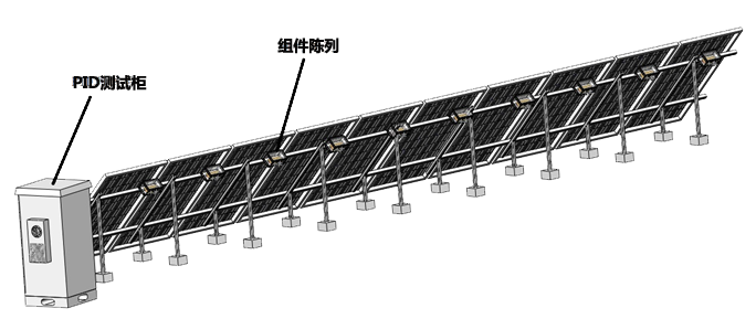
Test the PID of solar modules under actual outdoor conditions, and the power supply part meets the PID test requirement specified in the IEC62804 standard.
l The grounding of the module's frame end not only simulates the actual situation, but also prevents the potential danger caused by the high pressure of the frame during the test process.
l For each module, the high voltage wire is connected to the positive or negative electrode of the module. The negative wire is connected to the frame.
l Can set test time, and stop automatically.
l The screen shows the test situation, and record the test data;
l The system records temperature, humidity, irradiance, wind speed, wind direction and etc.
l Multiple currents are displayed at the same time, while alarm parameters are set individually, with single-circuit on/off control.
l Multi-channel voltage settings are programmed separately and the voltage can be set as required.
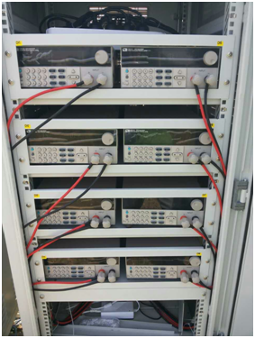
l Each component is connected to a resistor to allow the module to operate at its maximum operating point. The resistors are placed separately and the resistors are attached to the metal housing floor using heat sinks. This makes the resistor effectively dissipates heat. Resistor housing adopts IP65 grade, which has sufficient insulation effect.
Project | Parameters |
Voltage range | -1500V~0V/ 0~+1500V |
Source effect | ≤0.2% |
Time drift | ≤0.3%/h |
Temperature drift | ≤0.5‰/℃ |
Ripple | ≤0.5% |
Alarm setting range | 1~1000 uA /-1000 uA~1 |
Testing time | Can be set |
Insulation resistance | 1000MΩ |
Irradiance range | 0~2000W/㎡ |
Irradiance accuracy | ±5% |
temperature range | -50~200℃ |
Temperature accuracy | ±1℃ |
Temperature repeatability | ±0.5℃ |
Wind speed range | 0~70m/s |
Starting wind speed | ≤0.25m/s |
Wind direction range | 0~360° |
Wind direction resolution | 15° |
Humidity range | 20~100%RH |
Humidity accuracy | ±5%RH |


